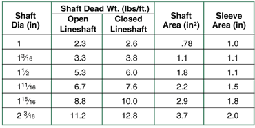
In addition to the impeller force, dead weight (shaft plus impeller weight less the weight of the liquid displaced) acts downward. On pumps with settings less than 50 feet, dead weight may be neglect-ed on all but the most critical applications as it represents only a small part of the total force. On deeper setting pumps, dead weight becomes significant and must be taken into account. NOTE:
We normally only take shaft weight into consideration as dead weight, the reason being that impeller weight less its liquid displace-ment weight is usually a small part of the total.
SHAFT SLEEVES
Finally, there can be an upward force across a head shaft sleeve or mechanical seal sleeve. In the case of can pumps with suction pressure, there can be an additional upward force across the impeller shaft area. Again for most applications these forces are small and can be neglected; however, when there is a danger of upthrusts or when there is high discharge pressure (above 600 psi) or high suction pressure (above 400 psi) these forces should be considered.
MOTOR BEARING SIZING
Generally speaking a motor for a normal thrust application has as standard, a bearing adequate for shutoff thrust. When practical, motor bearings rated for shutoff conditions are preferred. For high thrust applications (when shutoff thrust exceeds the standard motor bearing rating) the motor bearing may be sized for the maximum anticipated operating range of the pump.
Should the pump operate to the left of this range for a short period of time, anti-fraction bearings such as angular contact or spherical roller can handle the overload. It should be remembered, however, that bearing life is approximately inversely proportional to the cube of the load. Should the load double, motor bearing life will be cut to 1 ڸ of its original value. Although down thrust overloading is possible, the pump must never be allowed to operate in a continuous up thrust condition even for a short interval without a special motor bearing equipped to handle it. Such upthrust will tail the motor bearing.
CALCULATING MOTOR BEARING LOAD
As previously stated, for short setting non-hydraulic balanced pumps below 50 feet with discharge pressures below 600 psi and can pumps with Suction pressures below 100 psi only impeller thrust need be considered.
Under these conditions:
Motor Bearing Load (lbs.)
Timp= KHL, x SG
Where:
Impeller Thrust (lbs.)
K=Thrust factors (lbs./ft.)
HL = Lab Head (ft.)
SG = Specific Gravity
For more demanding applications, the forces which should be considered are impeller thrust plus dead weight minus any sleeve or shaft area force.
In equation form:
Motor Bearing Load = Timp + Wt(1) - sleeve force (2) -shaft area force(3) =Tt

(2) Sleeve Force=Sleeve area x Discharge pressure (3) Shaft Area Force = Shaft area x Suction pressure Oil Lube shaft does not displace liquid above the pumping water level and therefore has a greater net weight.
THRUST BEARING LOSS
Thrust bearing loss is the loss of horsepower delivered to the pump at the thrust bearings due to thrust. In equation form:
LTB = Thrust bearing loss (HP)
BHP = Brake horsepower
Tt = Motor Bearing Load (Lbs.)
= Timp+ Wt(1) - sleeve force(2) - shaft area force(3)


