Self-Priming Pump System Guidelines

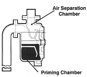
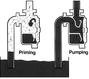
Self-priming pumps are inherently designed to allow the pump to re-prime itself typically under lift conditions. These pumps are very effective to the end user in that they will eliminate the need for foot valves, vacuum and ejector pumps which can become clogged or be impractical to use for prolonged or remote operation. Although the pump itself is designed to accomplish this task, it Is important to understand the principle of how self-priming is achieved so that the piping system can be designed so as not to conflict with this function. A self-priming pump, by definition, is a pump which will clear its passages of air if it becomes air bound and resume delivery of the pumpage without outside attention. To accomplish this, a charge of liquid sufficient to prime the pump must be retained in the casing (See Fig. A) or in an accessory priming chamber. When the pump starts, the rotating impeller creates a partial vacuum; air from the suction piping is then drawn into this vacuum and is entrained in the liquid drawn from the priming chamber. This air-liquid mixture is then pumped into the air separation chamber (within the casing) where the air is separated from the liquid with the air being expelled out the discharge piping (Fig. B) and the liquid returning to the priming chamber. This cycle is repeated until all of the air from the suction piping has been expelled and replaced by pumpage and the prime has been established (Fig. C).


sect b8 fig1
Fig. A


sect b8 figb figc
Fig. B / Fig. C
The following considerations should be made when designing a piping system for which a self-priming pump is to be used:


      ? Care should be exercised to insure that adequate liquid is retained In the priming chamber. For outdoor/remote installations a heating element may be required to prevent freezing. For dirty services a strainer may be required to keep solids from accumulating in the priming chamber, thus displacing priming liquid. ? The static lift and suction piping should be minimized to keep priming time to a minimum. Excessive priming time can cause liquid in the priming chamber to vaporize before prime is achieved.


      ? All connections in the suction piping should be leak-free as air could be sucked in, thus extending/compromising priming of the pump. (Pumps sealed with packing should be flushed to prevent air from being introduced.)


      ? A priming bypass line (See Fig. D) should be installed so that back pressure is not created in the discharge piping during priming which would prevent the pump from priming Itself. (Self-priming pumps are not good air compressors!)


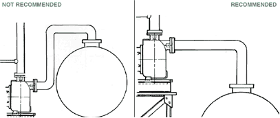
      ? The suction piping should be designed such that no high points are created where air can be trapped/accumulate which can prevent priming. Historically this has been problematic on top unloading of rail cars. (See Fig. E)
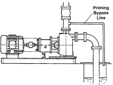
sect b8 figd
Fig. D


sect b8 fige
Fig. E Tank Car Unloading